XBot – All Grown Up

It’s autonomous now — no more tethering to your PC for power, except to recharge. This robot reacts to light with a dancing head and a micro light show. You control it by waving your hand around it. Since it runs on an Arduino Pro Mini it’s fully hackable. Source code and DIY instructions are on the way. The build is solderless: wire-wrap and hot-glue take care of everything in this low-powered bot.

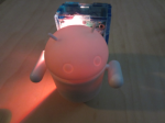
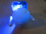
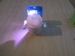
Three states are shown in the above photos. On (orange/red); Stand-By (blue); Dancing (shown as purple, but is multicolored).

Generic 3.3v BT Module BoB

Just in are a stack of breakout boards I designed for a cheap BT module sold on eBay. UPDATE: it’s taken a very long time to determine that this is either the EGBT-045MS or EGBT-046S from Cambridge Silicon Radio. The breakout is simple, breadboard-friendly, and exposes all 34 pins on the module. The bluetooth module runs on 3.3v and comes with SPP-compatible firmware — which basically means it’s compatible with Arduino and most MCUs. It’s not 5v tolerant and needs level-shifters for 5v systems. A 5v version with built-in shifters is in the works. The bluetooth module ships with a default baud rate of 9600.

For now I’m just posting resources to this page for this module:

  • Board Layout: bob_ebay_bt_module
  • Datasheet: egbt-045ms-046s Datsheet
  • Pseudo-datasheet (found in a few places online): Bluetooth Module_BC4_Blue V2.0
  • Master to Slave Connection Howto
  • AT command set: AT Commands for Bluetooth Module. Also, refer to datasheet for complete command set. Note, for this firmware you have to not send LF/CR (enter key) at the end of your AT command. AT programming mode is up when your board is not paired by bluetooth devices. You must copy/paste the AT command since timing is important. You can send about one command per second.
  • Example Application Schematic (see note):
    . Note: this schematic refers to an older module. Refer to the https://tenacious33.files.wordpress.com/2012/05/egbt-045ms-046s datasheet for the proper information on this module and proper application notes.
  • Application Example using this breakout board: .
    This circuit design is based on the manufacturer’s application note above, but the expected PIO pins didn’t provide any feedback for me. UPDATE: this design was built before the discovery of the true datasheet with proper application notes – but it’s still valid. It took a few minutes to find PIO for connection status on pin 24, not 31 (32?) as indicated. Also I can’t find a PIO for RX/TX status; but a LED + resistor in parallel on either/both RX and TX lines can help with that (not pictured here). Some things to note from the design include:
    • Connection status PIO pin is connected to the blue LED. Connection status LED blinks fast when not connected (command mode), solid when connected (serial mode).
    • This design uses a CP2102 USB breakout board to power everything and talk to the BT module. The breakout is available at Sparkfun. You don’t need the CP2102 to use the bluetooth module – 3.3v Arduino boards are particularly well suited, as is any MCU or other circuit that uses 3.3v. I have a 5v version in the works.
    • The RX/TX lines on the CP2102 and BT module are cross-connected – such as rx -> tx; tx -> rx.
    • Getting this setup working takes a few steps to verify:
      1. Connect to CP2102 using unix’s Screen command or other RS232/TTY application at baud rate of 38400. On OS X ZTERM is a popular RS232 application. On Windows I’ve heard the “sscom32” is recommended since the command’s timing is important. You need a terminal emulator that supports 38400,N,8,1.
      2. First, test the AT commands. Type AT+VERSION, you should see something like “linvor1.5”. There is no need to exit command mode. You may want to issue additional commands but be careful when you do, and finishing this checklist first is the recommended approach.
      3. Connect to BT module using a smartphone app that permits arbitrary messages to be sent via bluetooth — such as Amarino2 APK.
      4. Verify that the characters sent from phone appear on the PC.
      5. You should also be able to see characters typed from screen/tty-application to your phone. In Amarino2 you can use the “Serial Monitor” for sending and receiving bytes.
    • Porting the setup to other 3v3 Arduino or MCU is straightforward (explanation needed).
    • When using a phone or PC to connect to this Bluetooth module you should see it listed with names that start with “Linvor”. The connectivity on this module appears to be quite robust for the price point.
    • DO NOT connect anything higher than 3.3 volts to any input pin or power pin on this module. You will surely burnout that pin!